We initiate an object reference, we choose the image algorithm,
reconstruct the image, and plot the resulting image:
o = hsi_image()
o -> set,image_algorithm='forwardfit'
im = o -> getdata()
o -> plotman
Every setting of control parameters can also be specified by keywords, e.g.
im = o -> getdata(image_algorithm='forwardfit',/plot).
o -> plotman activates the Graphical User Interface (GUI), which can
be used instead of o -> plot
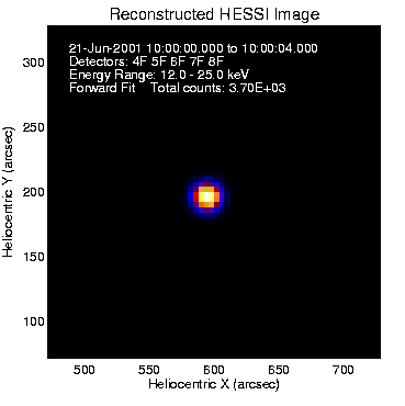
The resulting image shows a gaussian source at location [600,200] arcsecs offset from
the Sun, reconstructed with detectors 4-8 and in the energy range 12-25 keV.
Let us check the image control parameters, which we extract into the structure p,
and check parameters that are relevant for optimization of our image processing:
p = o -> get()
print,p.det_index_mask
.... e.g. [0,0,0,1,1,1,1,1,0,...]
print,p.energy_band
.... e.g. [12,25] keV
print,p.time_range
.... e.g. [0,4] s
print,p.xyoffset
.... e.g. [600",200"]
print,p.image_dim
.... e.g. [64,64]
print,p.pixel_size
.... e.g. [4",4"]
print,p.sim_xyoffset
.... e.g. [600",200"]
print,p.sim_model_ptr(0)
.... e.g. [1.0,0.001",0.001",0",0",0 deg]
print,p.sim_model_ptr(1)
.... e.g. [1.0,0.001",0.001",-12.",-12.",0 deg]
print,p.ff_n_gaussians
.... e.g. 1 (number of gaussian components)
print,p.ff_n_par
.... e.g. 4 (number of free parameters per component)
The simulation model parameter SIM_MODEL_PTR
is a structure that contains the normalized amplitude, the x and y gaussian
widths, the x and y positions, and the tilt angle of each gaussian component.
In our standard example we see that the
image contains two gaussian sources with equal amplitude (1.0), with a narrow width (x-width=0.001",
y-width=0.001"), one source at position [x,y]=[0.0",0.0"], and the second source at position
[x,y]=[-12.0",-12.0"], relative to the xyoffset=[600",200"].
There are a number of output parameters provided after an image reconstruction
with the forward-fitting algorithm has been completed. The quality of the
image reconstruction can be checked by the C-statistic value, which is similar
to the chi-square value and should be around 1.0. The C-statistic values are
listed for the time profile fits for each detector separately, and averaged together:
print,p.ff_chi_ff
.... e.g. [0,0,0,1.15,1.05,1.01,1.05,0.99,0] (C-statistic of 9 detectors)
print,p.ff_chiav_ff
.... e.g. 1.05 (average of C-statistics from used detectors)
The forward-fit coefficients are given in the structure P.FF_COEFF_FF, containing
1) the relative flux amplitude, 2) the gaussian width (in arcsec), 3) the x- and 4) the y-positiion
of the gaussian center relative to the map center (in arcsec), etc.
print,p.ff_coeff_ff
.... e.g. [1.00, 8.95", -4.11", -7.93"] (gaussian best-fit coefficients)
The solution is parameterized with 4 coefficients of a single gaussian component: the normalized
amplitude coeff(0,0)=1.00 (which corresponds to a flux given by P.FF_PEAK_FLUX*P.ALG_UNIT_SCALE
in units of incident photons/(s cm^2 asec^2), the gaussian
width of coeff(1,0)=8.95", and the coordinates of the centroid at x=-4.11" and y=-7.93",
relative to the map center at P.SIM_XYOFFSET=[600",200"].
We see that the single-gaussian fit located an intermediate position between the two true source
locations, with a gaussian width that is comparable with the distribution of the two combined sources.
The physical units of the flux in the image have been standardized between
different imaging algorithms (see HSI_IMAGE__ALG_UNIT.PRO).
The flux in these standard units is incident [photons/(s cm^2 asec^2)].
The same units are used GUI display (flux scale of scolor bar). To obtain the peak flux of
gaussian structures one has to multiply the relative amplitudes P.FF_COEFF_FF(0,*)
with the peak flux P.FF_PEAK_FLUX.
print,p.ff_peak_flux
.... e.g. A=0.20 [photons/(s cm^2 asec^2)] (peak flux in image)
The following constants given below are used for conversions between different flux units.
The product of the detector efficiency P.CBE_DET_EFF.AVG with the
pixel area P.PIXEL_AREA is combined in the parameter P.ALG_UNIT_SCALE.
det_area = hessi_constant(/detector_area)
.... e.g. det_area = 39.59 cm^2
det_eff = p.cbe_det_eff.avg
.... e.g. det_eff=0.246, (average detector efficiency)
pix_area = p.pixel_area
.... e.g. pix_area=16.0 (pixel area in asec^2)
print,p.cbe_det_eff.avg*p.pixel_area
... e.g. = 3.943 (combined scale factor)
print,p.alg_unit_scale
.... e.g. = 3.943 (algorithm unit scale)
The total count rate per sec and detector is given in the parameter P.FF_PHOT_SEC
in units of [photons/s].
Equivalently we can get this value by integrating over the entire image and multiplying
with the combined scale factor and detector area.
This should match the average of photon counts in the binned event list.
This number of photons incident per detector is less than the
number of simulated photons per detector (here P.SIM_PHOTONS_PER_COLL=10,000 photons/s),
because the number of simulated photons is defined before the detector response function.
print,p.ff_phot_sec
.... e.g. =680 photons/s
print,total(im)*p.alg_unit_scale*det_area
.... e.g. =680 photons/s
print,total(im)*p.pixel_area*p.cbe_det_eff.avg*det_area
.... e.g. =680 photons/s
print,p.binned_n_event(0:8)
.... e.g. =[783,691,454,752,663,872,621,738,544,681.] photons/s
print,avg(p.binned_n_event(0:8))
.... e.g. =680 photons/s
Warning: The total counts given in the current version of GUI (Jan 2002)
refer to the number of used detectors.
In this example the GUI gives "Total counts = 3.65E+03" for "Detectors: 4F 5F 6F 7F 8F".
Thus the photons/s for one single detector are 3650/5=730 cts/s.

Given the information about the simulated image we know that 2 gaussian components
should be used for the forward-fitting model. In real data, where the true source
structure is not known, we would use either the chi-square information from a
preliminary forward-fitting run or another quick imaging method (e.g. back-projection) to
guess a suitable number of source components. A perfect model would yield a chi-square
in the range of chi2=0.95...1.05. If the resulting chi2 is higher, it is justified to
increase the number of gaussian components. In the run above we find, e.g. a value of
C=1.05, which suggests to increase the number of free parameters, either a higher number
of source components (n_gaussians > 1) or a higher number of parameters (n_par > 4).
As a first attempt, we change the default value for the number or sources from N_GAUSSIANS=1
to N_GAUSSIANS=2. In addition, from the first run we see that we see that the source is very compact,
so we can reduce the field-of-view from 64x4"=256" to, say 64x1"=64". It is also advisable
to use the finer detectors for small sources that could be otherwise unresolved in a
compact source, so we enable all detectors a priori (the forward-fitting will
automatically select a subset of detectors with significant counts from the preset detector
set DET_INDEX_MASK). The photon statistics can also be improved by considering a larger
energy range, say E=[6,300] keV instead of the default range E=[25,50] keV.
An improved run may be attempted with:
o = hsi_image()
o -> set,image_algorithm='forwardfit'
o -> set,ff_n_gaussians=2
o -> set,pixel_size=[1,1]
o -> set,image_dim=[64,64]
o -> set,energy_band=[6.,300.]
o -> set,time_range=[0,4]
o -> set,det_index_mask=bytarr(9)+1B
im = o -> getdata()
o -> plotman
The best fit of the forward-fitting model with two gaussians is shown
in the time-domain, with the theoretical modulation profile (red curves)
on top of the obseved modulation profile (blue histograms):
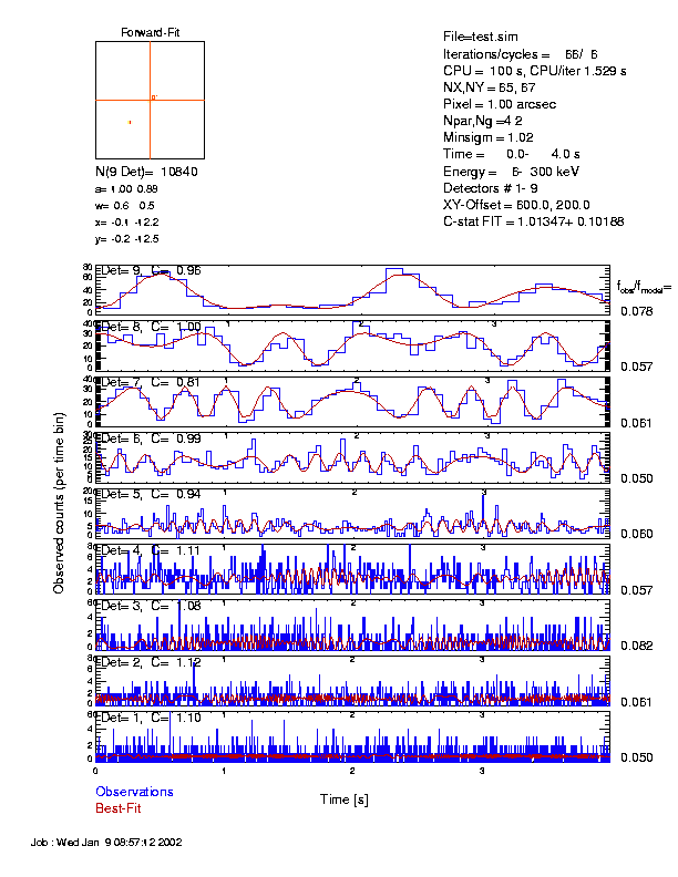
For this test we find the following values (you will get slightly different values because
there is a random generator used for the simulation of incident photons):
p = o -> get()
print,p.ff_n_gaussians
.... e.g. =2 (number of gaussian components)
print,p.ff_n_par
.... e.g. =4 (number of free parameters per component)
print,p.ff_chi_ff
.... e.g. =[1.10,1.11,1.08,1.11,0.93,0.99,0.81,1.00,0.96] (C-statistic)
print,p.ff_chiav_ff
.... e.g. =1.013
print,p.pixel_area
.... e.g. =1. asec^2 (pixel area)
print,p.ff_coeff_ff(*,0)
.... coefficients of first source, e.g. [1.00, 0.49", -0.08", -0.17"]
print,p.ff_coeff_ff(*,1)
.... coefficients of second source, e.g. [0.89, 0.51", -12.15", -12.48"]
The coefficients contain the following information:
[normalized amplitude, width, x-position, y-position].
So, we found the first Gaussian component with a normalized amplitude=1.0, width=0.5",
x,y=[-0.1",-0.2"], and the second gaussian component with amplitude=0.89, width=0.5",
x,y=[-12.1",-12.5]. Comparing these solutions with the simulation parameters we find agreement
of the location within ~0.2", which is satisfactory given the pixel resolution of 1".
Note that both point sources have a theoretical width of 0.001" and can therefore
not be resolved with HESSI.
The total flux is
print,p.ff_phot_sec
.... e.g. =1202 photons/s
print,total(im)*det_area*p.alg_unit_scale
.... e.g. =1202 photons/s
print,avg(p.binned_n_event(0:8))
.... e.g. =1243 photons/s
The absolute flux amplitude of each gaussian component
can be obtained by multiplying the normalized amplitudes P.FF_COEFF_FF(0,i) with
the peak flux P.FF_PEAK_FLUX/P.ALG_UNIT_SCALE in units of [photons/(s cm^2 asec^2)].
The amplitude of the primary and secondary gaussian A1 and A2 are given below.
Note that the maximum of the image, MAX(IM)=155, is smaller than the theoretical
amplitude A=190, because the source has a width smaller than the pixel size.
A = p.ff_peak_flux
.... e.g. A=190 photons/(s cm^2 asec^2)
A1 = A*p.ff_coeff_ff(0,0)
.... e.g. A1 = 190 photons/(s cm^2 asec^2) (of first gaussian)
A2 = A*p.ff_coeff_ff(0,1)
.... e.g. A2 = 168 photons/(s cm^2 asec^2) (of second gaussian)
print,max(im)
.... e.g. =155 photons/(s cm^2 asec^2)
The partitioned total fluxes of each gaussian component can be calculated
in three different ways. (1) The most accurate method is the analytical one,
according to the analytical integral of a 2D-gaussian, i.e.
Fi=Ai*2*pi*wi^2, where Ai are the amplitudes in units of [photons/(s cm^2 asec^2)]
and wi is the Gaussian width in units of [asec]. For the two gaussian components in the
example here we calculage the fluxes F1=351 and F2=251, which have a sum of F_total=F1+F2=602.
(2) A second method is to integrate over the image and multiply with the pixel-size,
which yields here also a fairly accurate value of A=TOTAL(IM)*P.PIXEL_AREA=601 [photons/(s cm^2)].
Note that the integral is well-conserved with both methods, although the peak amplitudes
(A=197 and MAX(IM)=102)
differ almost a factor of 2 because of the unresolved gaussian widths.
(3) A third method is to use the interactive flux integration option in GUI,
which yielded values [336 and 256 photons/(s cm^2)] for this case that are very
similar to the other methods. Also the sum [592 photons/(s cm^2)] was consistent
with the other methods within ~1%.
A1 = p.ff_peak_flux * p.ff_coeff_ff(0,0)
.... e.g. A1=190 photons/(s cm^2 asec^2)
A2 = p.ff_peak_flux * p.ff_coeff_ff(0,1)
.... e.g. A2=169 photons/(s cm^2 asec^2)
F1 = A1*2.*!pi*p.ff_coeff_ff(1,0)^2
.... e.g. = F1 = 283 (photons/(s cm^2) total flux of source 1
F2 = A2*2.*!pi*p.ff_coeff_ff(1,1)^2
.... e.g. = F2 = 308 (photons/(s cm^2) total flux of source 2
F_total = F1 + F2
.... e.g. F_total = 592 (photons/(s cm^2) (total flux of both sources)
print,total(im)*p.pixel_area
.... e.g. =600 photons/(s cm^2) (Integral over image)
The reconstructed incident number of photons/s can be calculated in three different ways
(see the 3 different commands below),
which give consistent values of ~1209 photons/s within ~2.5%.
print,p.ff_phot_sec
.... e.g. =1202 photons/s
print,total(im)*det_area*p.alg_unit_scale
.... e.g. =1202 photons/s
print,f_total*det_area*p.cbe_det_eff.avg
.... e.g. =1184 photons/s
print,avg(p.binned_n_event(0:8))
.... e.g. =1243 photons/s
Further insights into the fidelity of image reconstruction can be obtained by reconstructing the same image with other algorithms. Some test image comparisons are shown for backprojection, clean, and forward-fitting on the web-page:
Let's suppose you reconstructed a flare with the Graphical User Interface (GUI)
and wish to access the image IM and the image parameters (structure P), and
to save them in a IDL savefile.
This can be done via extracting the object reference o:
hessi_data,image=o
im = o -> getdata()
p = o -> get()
help,/str,p
save,filename='This_flare.sav',im,p