D. SCIENCE
Summary
The primary scientific objective of the High Energy Solar Spectroscopic Imager (HESSI) is to understand particle acceleration and explosive energy release in the magnetized plasmas at the Sun, processes which also occur at many other sites in the universe. The Sun is the most powerful particle accelerator in the solar system, accelerating ions up to tens of GeV and electrons to hundreds of MeV. Solar flares release up to 1032-1033 ergs in 102-103 s. The accelerated 10-100 keV electrons (and possibly >~1 MeV/nucleon ions) appear to contain a significant fraction, perhaps the bulk, of this energy, indicating that the particle acceleration and energy release processes are intimately linked. How the Sun releases this energy, presumably stored in the magnetic fields of the corona, and how it rapidly accelerates electrons and ions with such high efficiency, and to such high energies, is presently unknown.The hard X-ray/gamma-ray continuum and gamma-ray lines are the most direct signatures of energetic electrons and ions, respectively, at the Sun. HESSI will provide the first hard X-ray imaging spectroscopy, the first high-resolution spectroscopy of solar gamma-ray lines, the first imaging above 100 keV, and the first imaging of solar gamma-ray lines. HESSI combines an imaging system consisting of 9 rotating modulation collimators (RMCs), each with a high-spectral resolution germanium detector (GeD) covering energies from soft X-rays (3 keV) to high-energy gamma-rays (20 MeV). HESSI's hard X-ray imaging spectroscopy provides spectral resolution of ~1 keV, spatial resolution down to ~2 arcsec, and temporal resolution as short as tens of milliseconds. These parameters are, for the first time, commensurate with physically relevant scales for energy loss and transport of the >~10 keV electrons that are believed to contain much of the energy released in the flare.
HESSI's gamma -ray imaging spectroscopy will provide the first imaging of energetic protons, heavy ions, relativistic electrons, neutrons, and positrons; the first information on the angular distribution of accelerated ions; and detailed information on elemental abundances for both the ambient plasma and the accelerated ions.
With the fleet of spacecraft (SOHO, Wind, ACE, Ulysses, TRACE, GOES, Yohkoh, SAMPEX, CGRO, etc.) that will already be in place, a HESSI launch in mid-2000 would provide the crucial missing high energy measurements needed for comprehensive studies of the solar maximum.
A two-year nominal mission (a third year is highly desirable) will provide observations of tens of thousands of microflares, thousands of hard X-ray flares, and of order a hundred gamma -ray line flares. Rapid, direct access by the solar scientific community to the HESSI data and analysis software, together with a U.S. Guest Investigator program funded from HESSI MO&DA funds, plus extensive foreign participation, will ensure the maximum scientific return from this comprehensive data set.
HESSI will also obtain hard X-ray imaging of the Crab Nebula with ~2 arcsec resolution, and monitor a large fraction of the sky to provide, serendipitously, high spectral resolution observations of transient hard X-ray and gamma -ray sources, including accreting black holes, cosmic gamma-ray bursts, and terrestrial bursts from relativistic electron precipitation, aurora, and lightning.
HESSI's full-Sun field of view and storage of all information from every photon in a solid-state memory (sized to hold all the data from the largest flare) mean that flare data will rarely be lost and that mission operations can be automated. A 600-km altitude, 38° inclination circular orbit is baselined to allow uplink/downlink to a single ground station co-located with the Mission/Science Operations Center at the PI institution.
The extensive heritage from the UCB HIREGS and GSFC HEIDI balloon programs, and the UCB/GSFC FAST SMEX program, and recent NASA-funded technology development efforts, enable the HESSI instrument to be built with no new development. Spectrum Astro, our industry partner, will provide a simple, reliable, and inexpensive Sun-pointed spin-stabilized spacecraft based on subsystems already developed and flight-qualified from the Lunar Prospector, MSTI, MightySat, New Millenium, and FAST/SMEX programs. Thus HESSI is ready to be built within the SMEX cost and schedule constraints for launch in mid-2000.
The proposed mission concept has been endorsed by numerous advisory groups (e.g., NASA's Space Sciences Advisory Committee, and the National Academy of Science's Committees on Solar and Space Plasmas and on Solar Terrestrial Research), and was selected as a MIDEX alternate.
The HESSI team includes leading experts in solar high-energy spectroscopy and imaging, with decades of space hardware and data analysis experience. The team is committed to educational and public outreach, and has an outstanding record of involving young scientists/engineers, both graduate and undergraduate, as well as high school students and teachers.
D.1 Scientific Goals and Objectives
The processes of particle acceleration and impulsive energy release occur in active cosmic plasmas at diverse sites throughout the universe, ranging from planetary magnetospheres to active galactic nuclei. The understanding of these processes is a major goal of space physics and astrophysics, but we are just beginning to perceive the relevant basic physics. The Sun constitutes an unparalleled laboratory for investigating these processes. Its proximity allows measurements over the entire wavelength range to be made on physically relevant scales. At the same time, the system as a whole can be studied, and escaping energetic particles and plasma can be sampled directly. Further, the complexity of solar magnetic fields and the solar atmosphere leads to a broad range of acceleration phenomena, mirroring the rich diversity of processes occurring on cosmic scales.Solar flares are the most explosive of these phenomena. High-energy emissions are the most direct signature of the acceleration of electrons, protons and heavier ions in solar flares. The hard X-ray and gamma-ray continuum is produced as bremsstrahlung by energetic electrons. Nuclear collisions of energetic ions with the ambient solar atmosphere result in a complex spectrum of narrow and broad gamma-ray lines that contain unique information on not only the accelerated ions but also the ambient solar atmosphere.
HESSI will have sensitivity and dynamic range sufficient to provide meaningful observations from microflares and the earliest emissions from a flare, to the peaks of the largest flares. The high spectral and spatial resolution of these observations will permit, for the first time, the deciphering of the rich information encoded in both the gamma -ray lines and the highly structured photon continuum. These high-energy emissions are accompanied by longer wavelength emissions, and sometimes by escaping energetic particles. Their observation by the fleet of spacecraft that will already be in place, and by ground based instruments, will provide the crucial information on the context in which the high energy processes occur.
Particle Acceleration and Energy Release
Bursts of hard X-rays (>~20 keV) are the most common signature of the impulsive phase of a solar flare (Fig. D-1). These X-rays are bremsstrahlung, produced by accelerated electrons colliding with the ambient solar atmosphere. If these electrons are indeed nonthermal (i.e., electron energy Ee>>kT of the ambient gas), then the energy lost by the electrons to bremsstrahlung in collisions with ambient ions is only a small fraction (~10-5) of their energy lost to Coulomb collisions with ambient thermal electrons. This inefficiency means that, for many flares, the energy in accelerated >20 keV electrons must be comparable to the total flare radiative and mechanical output (Lin and Hudson 1976). Thus the acceleration of electrons to tens of keV may be the most direct consequence of the basic flare-energy release process.
Figure D-1. Time profiles for a flare showing near- coincidence impulsive peaks in 35-114 keV hard X-rays (from energetic electrons) and 4.2-6.4 MeV gamma-rays (from energetic ions).
It is, however, still possible that a fraction of the hard X-rays at tens of keV is quasi-thermal, i.e. produced by a Maxwellian population of electrons with Ee » kT with T >~ 108 K. Then the energy lost by one electron in an electron-electron Coulomb collision simply increases the energy of the other. In that case, the principal losses are due to conduction and convection, which can be considerably less than the collisional losses in nonthermal models. HESSI will determine the relative contribution of thermal and nonthermal emission to the hard X-ray spectrum.Hard (>20 keV) X-ray microflares, 10 - 100 times less intense than small flares, occur every ~5 minutes (Lin et al. 1984) near solar maximum, with the smaller ones occurring more frequently. Recently, high sensitivity measurements down to ~8 keV with the CGRO BATSE experiment show that solar impulsive bursts are observed >~3 times more often above 8 keV than above 25 keV (Lin 1997). Essentially every active region transient brightening in thermal soft X-rays (Shimizu, 1995) is accompanied by an impulsive, nonthermal >8 keV burst. This suggests that the flare process may be a fundamental way by which stored magnetic energy is transiently released in the Sun's corona (Parker 1988). If the nonthermal spectra extend down to ~5 keV, the average rate of energy deposition by microflare accelerated electrons, assuming nonthermal X-ray production, could be a significant fraction of that required to heat the active region corona. HESSI's high sensitivity imaging spectroscopy extending down to ~3 keV will allow the systematic survey of the microflare non-thermal contribution to coronal heating. At the same time these "simple" microflares may provide unique insights into the basic flare acceleration and energy release processes.
Non-Relativistic Electron Acceleration
During the flare impulsive phase, the Yohkoh Hard X-ray Telescope (HXT) often observes double footpoint structures (Fig. D-2), with the two footpoints brightening simultaneously to within a fraction of a second (Sakao et al. 1994). These coincide, spatially and temporally, with H-alpha and white-light brightenings.For some flares occurring near the solar limb, HXT has detected a co-temporal, weaker, hard X-ray source in the corona (Masuda et al. 1994; Alexander and Metcalf, 1997) above the soft X-ray loop linking the hard X-ray footpoints (Fig. D-2). This source has been interpreted as evidence for energy release by magnetic reconnection in a region above the soft X-ray loop.
Very rapid transport of energy from the release site down to the footpoint interaction regions is required. This can only be achieved by fast electrons streaming down the loop and depositing their energy in lower coronal and chromospheric footpoints, implying that nonthermal, tens of keV electrons are interacting with a cool (T<105 K) environment. The resulting heating of the ambient gas leads to evaporation of chromospheric material and flare radiation in the visible, UV/EUV and soft X-rays. Hard X-ray studies of electron time-of-flight (Aschwanden et al. 1996a,b,c) further support this nonthermal thick target model, but it is unclear how the implied huge currents (up to 1036 electrons/s or 1017 amps) can conform to the global electrodynamic constraints of the flare environment (Miller et al. 1997). HESSI's hard X-ray imaging, with much higher dynamic range and temporal and spectral resolution than Yohkoh HXT, is needed to study these coronal sources and electron streaming in detail.
D-2 . The M1 limb flare seen with Yohkoh SXT and HXT. Top center: A, model flare ten times more intense, expected to occur once a month on average at solar maximum. The thick and thin contours are for hard and soft X-rays, respectively. Bottom: Simulation results showing reconstructed images for Yohkoh (left) and HESSI (center) with soft X-rays, point-spread function (50%) indicated. Right: Spectra at different locations with HESSI's spectral resolution and with the four HXT energy channels. Note that HESSI (but not HXT) has sufficient dynamic range capability (up to 100:1) to obtain spectra from the legs of the loop in the presence of the bright footpoints.
Comparisons of microwave images with Yohkoh HXT images show a striking tendency for flares with three footpoints, i.e. in which two loops of different sizes appear to share a common footpoint (Nishio et al. 1997), suggesting loop-to-loop interactions. Typically the two loops have quite disparate sizes, with the longer loop (remote footpoint) initially visible only in hard X-rays. HESSI's full-Sun observations, with high spatial and temporal resolution and wide dynamic range, are key to understanding the energy release in loop-loop interactions.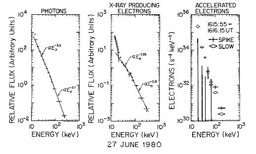
Figure D-3. High-resolution X-ray spectrum for 27 June 1980 flare (left) with the derived spectra of the X-ray producing electrons [N(E)] (center) and the accelerated electrons [F(E)] (right) (from Johns and Lin 1992).
As we show below, high resolution X-ray imaging spectroscopy is the key to understanding the acceleration and energy release processes. Precise measurements of the solar flare hard X-ray spectrum can be directly inverted to obtain the detailed spectrum of the parent X-ray-producing electrons at the Sun. The scintillation (NaI or CsI) detectors used for all previous spacecraft solar hard X-ray observations are inadequate for this task, but cooled GeDs with their near delta-function response for continuum measurements are ideal.The first (and only) high-spectral resolution hard X-ray measurement, obtained with a balloon-borne GeD spectrometer on 1980 June 27 (Fig. D-3, left), immediately led to the discovery of a "superhot" ~3.5 x 10⁷ K thermal source (Lin et al. 1981). It also showed that the nonthermal component does not fit a single power law or a single temperature thermal, but has a relatively sharp break at ~50 keV.
Johns and Lin (1992) showed that these data can be numerically inverted to determine N(E,t), the parent electron spectrum (Fig. D-3, center). N(E,t) is the result of modification of the accelerated electron spectrum F(E,t) by electron energy loss, propagation, and escape processes. Assuming that Coulomb collisions dominated these loss processes, Lin and Johns (1993) derived F(E,t) and found two separate components of accelerated electrons: an impulsive spike component with a spectrum peaked at ~50 keV, plus a slowly varying component with a power-law spectrum extending down to ~20 keV (Fig. D-3, right).
The peak in the spike electron spectrum suggests acceleration by a DC electric field, with the peak energy corresponding to the total potential drop in the field; such electron spectra are observed in the Earth's auroral zone. Comparison of the observed thermal "superhot" and nonthermal hard X-ray spectra with a model of heating and runaway electron acceleration in a DC electric field (Benka and Holman 1994) allowed determination of the electric-field strength, plasma density, and temperature in the flare.
HESSI will provide the crucial key for determining the particle acceleration process, namely the spectral, spatial, and temporal variation of the accelerated electrons, F(E,r,t). The 2-arcsec and tens-of-millisecond resolutions of HESSI are commensurate with the spatial and temporal scales for the accelerated electrons to lose their energy in the lower corona and upper chromosphere (ambient densities below ~1012 cm-3). With HESSI's high energy resolution, the photon spectrum in each spatial and temporal element can be directly inverted to obtain N(E,r,t), the X-ray producing electron number density, as a function of energy (E), position (r), and time (t).
N(E,r,t), together with information on ambient density, magnetic field strength and topology, will allow the electron loss processes to be directly evaluated. This will decide whether the X-ray emission is thermal or nonthermal, since the energy loss characteristics of the emitting electrons are so different in the two cases. Then, via transport calculations (using a spatially dependent continuity equation including loss processes), the spatially and temporally resolved accelerated electron source distribution, F(E,r,t), can be obtained. Once N(E,r,t) and F(E,r,t) are obtained, detailed quantitative models of the acceleration, energy release, and energy propagation processes can be constructed and tested. This powerful technique is generally applicable to HESSI's hard x-ray continuum measurements.
Non-imaging hard X-ray observations have already shown, via limb occultation, that the upper corona may be the source of hard X-ray emission of a different type (Hudson 1978), which may continue for tens of minutes (Cliver et al. 1986) and extend to altitudes of some 160,000 km (Kane et al. 1992). This emission could require as many as 1039 electrons above 5 keV with a total energy of 1031 ergs in a volume 1030 cm3. HESSI will provide N(E,r,t) for this source to decide whether it is related to the passage of shocks through the corona.
Impulsive Solar Energetic Particles (SEP) Events
Solar Energetic Particle (SEP) events observed in the interplanetary medium (IPM) are of two types, impulsive and gradual, so-called because of the temporal behavior of the associated flare soft X-ray burst (Lin 1987, 1994). Impulsive SEP events (~103/year at solar max) are rich in ~1-102 keV electrons and 3He (Reames et al. 1985), with enhanced abundances of heavy ions (Fe, Mg, Si, S) and high ionization states (e.g. Fe+20), suggesting high temperatures or stripping.These events are generally associated with small flares, and solar type III radio bursts. The electrons escaping through the corona and IPM generate plasma waves, which, in turn, combine to produce the radio emission (see Lin 1990 for review). How the electron beam can propagate to >~1 AU without losing all its energy to the plasma waves is not known. Soft X-ray jets, recently discovered by Yohkoh (Shibata et al. 1992) turn out to be the dense channels in which some type III bursts propagate (Kundu et al. 1995). The spectra of the escaping type III electrons observed in the IPM are power-laws extending down to ~1 keV before a turnover, indicating a high coronal origin (Lin et al. 1996). Comparisons of HESSI's determination of N(E,r,t) at the Sun down to a few keV with soft X-ray images and electron measurements in interplanetary space will help in understanding the electron acceleration, escape, and radiation processes, as well as the origin of the 3He enhancements.
Relativistic Electron Acceleration
Relativistic electrons have been detected in solar flares by observations of bremsstrahlung continuum emission extending up as high as several hundreds of MeV. At energies of a few hundred keV the spectrum often shows a flattening, indicating that a different mechanism may be accelerating the relativistic electrons. HESSI will provide the first imaging in the energy range above 100 keV.Electrons of energies from a few hundred keV to several MeV also produce gyrosynchrotron radiation in the microwave and mm-wave region. Recently, impulsive spikes of mm-wave emission, implying relativistic electron acceleration, were detected by BIMA for even small flares (Kundu et al. 1990). Because the ratio of the magnetic field to the ambient density is much higher in the coronal part of loops than in the footpoints, the centroids of the microwave and soft gamma -ray sources will likely be spatially distinct. Comparison of N(E,r,t) obtained by HESSI with the spatial distribution, fluxes, and spectra of the microwaves and mm-waves, will provide information on the angular distribution of the electrons, on the magnetic field strength, and on the acceleration, trapping, and precipitation of the electrons.
Ion Acceleration
Near the Sun, nuclear collisions of accelerated protons, alpha -particles, and heavier nuclei with the ambient solar atmosphere result in a rich spectrum (Fig. D-4 and Table D-1) of lines (Ramaty and Murphy 1987). gamma -ray line emission has been observed from many solar flares, mostly by the Solar Maximum Mission (SMM) (Chupp 1990; Share and Murphy 1995). Energetic protons and alpha-particles colliding with carbon and heavier nuclei produce narrow de-excitation lines (widths of ~ few keV to ~100 keV), while energetic heavy nuclei colliding with ambient hydrogen and helium produce much broader lines (widths of a few hundreds keV to an MeV). Neutron capture on hydrogen and positron annihilation produce narrow lines (at 2.223 MeV and 0.511 MeV, respectively) which are delayed. HESSI will probe ion acceleration with the first high-resolution spectroscopy of solar flare gamma-ray lines and the first imaging of solar flare gamma-rays. HESSI's GeDs can spectrally resolve all the expected lines except the 2.223-MeV line (see foldout Fig. D11-J at end of section); none of these lines have been resolved by the solar gamma -ray detectors to date.Table D-1. HESSI response for gamma -ray lines from a large flare (4 June 1991), and 3 sigma sensitivities (4th column).
|
|
|
Width (keV) | 3 sigma Line Fluence (ph/cm2) |
|
|||
|
|
HESSI Line Counts | HESSI Continuum Counts* | Number of sigma | ||||
| Prompt lines | |||||||
|
|
|
|
|
|
|
|
|
|
|
|
|
|
|
|
|
|
|
|
|
|
|
|
|
|
|
|
|
|
|
|
|
|
|
|
|
|
|
|
|
|
|
|
|
|
|
|
|
|
|
|
|
|
|
|
|
|
|
|
|
|
|
|
|
|
|
|
|
|
|
|
|
|
|
|
|
|
|
|
|
|
|
|
|
|
|
|
|
|
|
|
|
|
|
|
|
|
|
|
|
|
|
|
|
|
|
|
| Delayed lines | |||||||
|
|
|
|
|
|
|
|
|
|
|
|
|
|
|
|
|
|
* For most lines, about 90% flare continuum and 10% instrumental background for this bright flare.
**The narrow lines are for a downward beam or a fan beam; the single broad line at ~0.45 MeV is for an isotropic distribution.
*** This line has an intrinsic width of ~0.1 keV, so we used the instrument FWHM resolution (2.5 keV).
HESSI will provide the first determination of line shapes, which are direct probes of the angular distribution of the interacting accelerated ions. The derived angular distributions will discriminate between various transport and acceleration mechanisms. For example, ions which suffer strong pitch-angle scattering into loss cones due to plasma turbulence in the coronal part of the loops will mostly interact while going downward and produce different line shapes than ions which interact while mirroring near the loop footpoints.The shape of the 0.511 MeV positron annihilation line gives information about the ambient medium since the positrons slow down before annihilating. HESSI's energy resolution at 0.511 MeV is sufficiently good to measure temperatures down to 104 K, and it can easily distinguish among annihilation sites located below the transition region, in the corona, or in the hot (~107 K) flare plasma. The bulk of the annihilations would occur in the corona if the magnetic field traps the positrons there. Measurements of a positronium continuum below 0.511 MeV (from 3-photon decay), which is prominent only if the density of the ambient medium is less than ~1015 cm-3 (Crannell et al. 1976), will show whether energetic ions have penetrated to regions of high density (Hua et al. 1989).
HESSI has a unique capability to image in narrow gamma -ray lines, where line counts dominate over the background (Table D-1). Thus, both the 2.223 MeV neutron capture and 0.511 MeV positron annihilation lines can be imaged. Although gamma-ray lines have never been directly imaged, the 2.223 MeV line was once detected in a behind-the-limb flare (Vestrand & Forrest 1993). This line is formed when thermalized neutrons are captured by ambient protons in the photosphere, at a much greater depth than that at which nuclear reactions take place. Because of the very strong expected attenuation, the neutrons must have been produced by charged particles interacting on the visible hemisphere of the Sun. Thus, either the acceleration site was far removed from the optical flare site, or the charged particles were transported over large distances.
The continuum above 1 MeV (especially 4-7 MeV) is often dominated by the broad lines from accelerated heavy (Z>2) ions, and can be mapped to localize them. In a large gamma-ray line flare with good statistics, the >3 MeV protons can be located by imaging the 20Ne de-excitation line. Locations and source sizes will be determined in large flares to ~35 arcsec, allowing footpoints to be identified. HESSI's gamma-ray images will provide crucial information on acceleration and transport of energetic heavy ions and protons.
HESSI's high energy resolution allows it to separate closely spaced lines (e.g. 1.634 and 1.778 MeV), but more importantly it dramatically increases the sensitivity for detecting very narrow lines (e.g., the 2.223 MeV line). By observing the ratio between the 2.223 MeV line and the bremsstrahlung continuum in many flares, HESSI will test whether ions are accelerated in all flares, down to much lower flux thresholds than with SMM.
The bulk of the gamma -ray line emission is produced by ions with energies of 10-100 MeV/nucleon that contain only a small fraction of the energy in the ~>20 keV electrons. However, systematic study of SMM gamma -ray line flares (Share and Murphy 1995) shows that the 1.634 MeV 20Ne line is unexpectedly enhanced. Because the cross section for 20Ne has an unusually low energy threshold (~2.5 MeV), this effect may be due to large fluxes of low-energy ions with a total energy content perhaps comparable to that in accelerated electrons, rather than to an overabundance of neon (Ramaty et al. 1995; Emslie et al. 1997). HESSI will provide the first high-resolution spectroscopy and imaging of the 20Ne line. The ratio of the flux in this line to other lines will probe the ion energy spectrum (and total ion energy content) down to ~1 MeV.
If DC electric fields accelerate the hard-X-ray-producing electrons, then they may also accelerate many 100-keV protons (Holman 1995). Optical H-alpha polarization is highly sensitive to low-energy (100 keV) protons. Positive detections of H-alpha polarization in a few flares have been made (Henoux et al. 1990), but their interpretation is uncertain. With simultaneous HESSI ion and electron images and H-alpha polarization maps, the partition of energy between accelerated electrons (derived from hard X-ray measurements) and ions may be measured for the first time.
A very important discovery during Cycle 22 was that of long-duration gamma -ray emission. GeV gamma -rays from pion decay were observed with EGRET on CGRO for up to 8 hours after the impulsive phase of the 11 June 1991 flare (Kanbach et al. 1993). Nuclear line emission at 2.223 MeV was also observed with essentially the same time profile (Rank 1996). This strongly suggests that acceleration to GeV energies was ongoing for a very long time. With its sensitivity, HESSI will observe the 2.223-MeV line for several hours after a flare similar to the 11 June flare. These observations will address the issue of particle trapping vs. continuous acceleration in flares.
Time variation of the 2.223-MeV line can also be used to determine the unknown 3He abundance in the photosphere. 3He has a very high cross section for neutron capture and removes neutrons from the population which produces the 2.223 MeV line. Not only is the line flux reduced, but its time profile is changed in a way that can be compared to models (Hua & Lingenfelter 1987). The solar 3He abundance is essential for studies of galactic abundance evolution and may have cosmological implications. Even though the coronal 3He/4He ratio is measured in the solar wind, the gamma -ray observations provide a direct measure of the photospheric abundance.
Alpha particle interactions with ambient He produce 7Be and 7Li in excited states leading to line emission at 0.429 and 0.478 MeV. SMM detected larger-than-expected fluences of these lines (Share & Murphy 1997; Mandzhavidze et al. 1997). Either the abundance of accelerated alpha-particles is higher than expected from SEP observations (Reames 1994), or the abundance of ambient helium is much higher than the photospheric values obtained from both helioseismology (Hernandez & Christensen-Dalsgaard 1994) and the standard solar model (Bahcall & Pinsonneault 1995). HESSI can detect a narrow line at 339 keV due to the bombardment of 56Fe by energetic alpha-particles leading to 59Ni in an excited state (Fig. D-4). This will distinguish between enhanced alpha-abundance in accelerated particles or in the ambient medium.
Acceleration due to gyroresonant interactions with plasma turbulence in impulsive flares is hypothesized to be responsible for the large e/p ratios and 3He enrichments (Temerin and Roth 1991). The enrichment of heavy-element (in particular Fe) abundances in SEPs is another signature of impulsive flares (Reames et al. 1994). Also, SMM observations (Share & Murphy 1995) have shown that the abundance ratio of low FIP (Mg, Si, Fe) to high FIP (e.g., Ne) elements is enhanced in the de-excitation region relative to the photosphere (Ramaty et al. 1995), as is already is known for the corona from SEP measurements. Comparing HESSI's gamma-ray determination of e/p and elemental abundances (both in accelerated particles and in the ambient medium) at the Sun, with IPM measurements of the composition of SEPs will test the hypothesis that gamma-ray flares and impulsive SEP events have a common origin (Ramaty et al. 1993).
Large Solar Energetic Particles (SEP) Events
Gradual SEP events (tens per year at solar max) are generally large (hence also called LSEP) events dominated by protons, with "normal" solar abundance and ionization states typical of quiet 1-2 ´ 106 K corona, (e.g. Fe+13). These are associated with large flares and fast Coronal Mass Ejections (CME's) driving shock waves in the IPM.In the most intense LSEP events, the fluence of protons sufficiently energetic (>~50 MeV) to penetrate the walls of manned spacecraft is high enough to result in a harmful or even fatal radiation dose to astronauts. Such intense events also degrade electronic components on unmanned spacecraft. SEPs can also penetrate deep into the atmosphere over the Earth's magnetic polar regions and produce increased ionization, lowering the ionosphere and disrupting radio communications.
The >~50 MeV proton flux in classic LSEP events generally shows a rapid onset within about the particle travel time after a large flare, indicating that the acceleration occurred close to the Sun at about the time of the flare. LSEPs are thought to be accelerated by CME shocks close to the Sun (Reames 1996). In the IPM, however, CME shocks appear to accelerate particles only up to ~10 MeV, but not to >~50 MeV, unless an energetic seed population is already present.
Studies by the NOAA Space Environment Center (SEC) show that the best current predictor of LSEPs is the systematic spectral hardening with time of the flare hard X-ray burst (Kiplinger 1995). The soft X-ray long-duration events (LDE) associated with LSEP events appear to have hard X-ray emission in about the same proportion as in impulsive events (Dennis and Zarro 1993; Hudson et al. 1994). It is not clear how this LDE hard emission relates to the impulsive flare burst.
Recently, the SOHO EIT has observed the "Moreton wave" phenomenon of blast waves radiating directly from a flare site (Thompson et al. 1997). Shocks in the corona within about 3 solar radii produce metric type II solar radio bursts. These are flare-related and evidently not related to fast CMEs (Wagner and McQueen, 1983; Gopalswamy and Kundu, 1995; Gopalswamy et al. 1997). HESSI hard X-ray and gamma-ray spectroscopy and imaging, together with observations of coronal shocks, SEPs, and CMEs, are needed to understand the various ion acceleration processes at the Sun and their relationship to flare electron acceleration, and for more accurate prediction of LSEP events.
Context Observations
For interpreting HESSI's observations, knowledge of the physical parameters in the regions of interest is essential. Imaging spectroscopy (down to 3 keV) by HESSI itself will reveal the temperature, density, location, and temporal evolution of flare thermal plasmas, as well as the characteristics of the low energy (<20 keV) accelerated electrons that may contain the bulk of the energy released.The Soft X-ray Imager (SXI), to be launched in early 2000 on a GOES spacecraft (and SXT on Yohkoh if still operational), will provide broad-band (6-60 Å) images to determine the global and local morphology of coronal features.
SOHO's EIT and CDS will provide EUV images and spectra that give the temperature, emission measure, density, and velocity of plasma in the chromosphere, transition region, and corona at temperatures ranging from ~2 x 10⁴ K to ~2 x 10⁷ K. SOHO/LASCO will provide evolution, mass, momentum, and energy transport information on any coronal activity, particularly CMEs, that may result in particle acceleration. SOHO/MDI and ground-based instruments will provide measurements of magnetic field strengths in the photosphere.
SEP and solar wind composition measurements will be provided by Wind, ACE, SOHO, SAMPEX, and Ulysses. Wind and Ulysses also provide IP radio measurements. For a HESSI launch in mid-2000 the required space context observations will be available from the spacecraft that will already be in place.
Microwave and mm-wave imaging/ spectroscopy will provide direct measurements of preflare coronal magnetic fields plus thermal and nonthermal electron parameters. Vector magnetograms will show the role of evolving magnetic fields (e.g., emerging magnetic flux) and provide maps of electric currents to define their relationship to sites of possible DC electric field acceleration (Canfield et al. 1993). Optical imaging spectra provide velocities in the lower atmosphere, a straightforward measure of the energy that goes into chromospheric evaporation. Multiband optical imaging will provide information on energy release, since the optical continuum emission is thought to be the largest component of the radiative energy budget of flares. Imaging H-alpha polarization measurements may provide a way to detect ~100 keV accelerated protons. HESSI will provide support to ensure that key ground context observations of the needed quality are available.
Non-Solar Science
Although designed as a solar instrument, HESSI provides a combination of ~keV resolution, ~150 cm2 collecting area, and wide field of view (at 60° - 120° to the solar direction) that makes it complementary to the ESA INTEGRAL mission, which will have a narrow field of view.HESSI will be an effective high spectral resolution hard X-ray/gamma-ray all-sky monitor, allowing identification of transients (black-hole X-ray novae, Be/neutron star binary outbursts, etc.) within days using occultation. It benefits from the spacecraft's rotation, which will produce many detector/detector occultations per minute, as well as from two brief Earth occultation periods per orbit (Harmon et al. 1992; Zhang et al. 1993). HESSI will be able to resolve cyclotron absorption features from bright transients such as A0535+26, and the line shapes will test models of the neutron star polar region. HESSI can also search for the line features between 10 and 100 keV reported by Ginga in gamma-ray bursts but not confirmed by BATSE (Band et al. 1994), and study the Galactic positron annihilation and 26Al decay lines on angular scales larger than the INTEGRAL field of view.
Once a year a small offset pointing of HESSI (<1° ) would result in imaging of the Crab Nebula with unprecedented spatial (2 arcsec) and energy (~1 keV) resolution. Although the nebula shows intricate structure from radio through UV, with a tendency toward smaller sizes at higher energies, it has been imaged in hard X-rays only once (Pelling et al. 1987), with only 15 arcsec resolution and two energy bands. One day of HESSI observation would give ~2 x 10⁵ source counts from 25-35 keV, for ~300 sigma of total flux in the map. Maps could be made up to ~200 keV. Yearly maps can show changes; significant changes in structure have been seen in the radio and optical bands (Bietenholz & Kronberg 1992).
HESSI will also provide high spectral and temporal resolution measurements of terrestrial X-ray/gamma-ray emissions from relativistic electron precipitation (Smith et al. 1995), auroral precipitation, and bursts associated with lightning (Fishman et al. 1994).
Expected Results
The total HESSI effective photopeak area (foldout Fig. D-11G) and response to a large flare (Fig. D-4 and Table D-1) were obtained with detailed Monte Carlo calculations, using the GEANT code and taking into account the grids and all known materials in the cryostat and detector modules. The orbit-average background (Fig. D-4) was similarly computed and is consistent with scaling from balloon-borne GeD measurements.The total count rates are shown in Fig. D-5 for the front and rear GeD segments. The turnover in the count rates at high photon fluxes are due to dead-time from the pulse pile-up rejection used to eliminate resolution degradation. Broadband imaging with ~10 keV resolution for the GeD front segment extends the dynamic range to a 20 keV X-ray flux of ~3x104 cm-2 s-1 keV-1, while the GeD rear segment can handle flares with three times higher flux, or up to ~30 to ~100 times larger than the 27 April 1981 gamma -ray line flare. Thus, HESSI is the first solar high energy instrument to have the dynamic range to both detect microflares and make quantitative spectral measurements of the largest flares.
Figure D-5. Integral flare size distribution with 20 keV X-ray flux, for the flares and microflares observed in 1980; and corresponding HESSI total (9 GeDs) counting rates for front and rear segments.
Assuming HESSI observes the Sun 60% of the time, and with the predicted HESSI background, ~102 microflares per day will be detectable above a 20-keV photon flux of ~5x10⁻³ photons cm-2 s-1 keV-1. Since a minimum of about a hundred source counts is needed to form a simple image, the location and size of microflares could be determined for ~40 events/day, with fluxes about three times larger than threshold.For ~2 events / day with >~103 counts s-1 above 15 keV, rapid spatial changes of the hard X-ray sources could be followed with simple images on time scales of 0.1 s, or full-Sun spectroscopic studies with no imaging (e.g., Lin and Johns 1993) could be carried out to obtain N(E,t). Detailed imaging spectroscopy providing N(E,r,t) could be done with images in each of ten energy intervals with ~2-s time resolution for one event every ~5 days with >~104 counts s-1 above 15 keV; crude imaging information could be obtained in tens of milliseconds.
Assuming that every flare accelerates ions with fluxes proportional to the hard X-ray flux, the calculated 3 sigma sensitivities (Table D-1) imply that the 2.223-MeV line should be detected, on average, once every ~4 days, the 0.511-MeV line every ~14 days, and prompt de-excitation lines every ~21 days.
The source location and size could be obtained every ~13 days for the 2.223-MeV line, and once every ~60 days for the 0.511-MeV line and the nuclear continuum from energetic heavy ions. Detailed spectroscopy revealing many gamma -ray lines will be possible for these flares, allowing the abundances of many elements to be determined.
Every six months, a flare can be expected that is sufficiently large to locate the source of emission of narrow prompt de-excitation lines from energetic protons. Thus, tens of thousands of microflares, thousands of hard X-ray flares, and of order a hundred gamma -ray line flares will be detected in the HESSI 2-year operating lifetime.
D.2. Science Implementation
D.2.a Instrumentation
The HESSI scientific objectives will be achieved with high resolution imaging spectroscopy observations from soft X-rays to gamma -rays, utilizing a single instrument consisting of an Imaging System, a Spectrometer, and the Instrument Electronics. The Imaging System is made up of nine Rotating Modulation Collimators (RMCs), each consisting of a pair of widely separated grids mounted on a rotating spacecraft (Fig. D-11K). Pointing information is provided by the Solar Aspect System (SAS) and Roll Angle System (RAS) (Fig. D-11K,M).The Spectrometer (Fig. D-11N) has nine segmented GeDs, one behind each RMC, to detect photons from 3 keV to 20 MeV. The GeDs are cooled to <~75 K by a space-qualified long-life mechanical cryocooler (Fig. D-11Q) to achieve the highest spectral resolution (Fig. D-11J) of any presently available gamma -ray detector. As the spacecraft rotates, the RMCs convert the spatial information from the source into temporal modulation of the photon counting rates of the GeDs. The Instrument Electronics amplify, shape, and digitize the GeD signals, provide low-voltage power and GeD high voltage, format the data, and interface to the spacecraft electronics. Essentially all of the HESSI instrument components have extensive flight or life-cycle heritage (Table D-2).
| Spectrometer | |
| Germanium Detectors | HIREGS, HEXAGONE |
|
|
HIREX, HIREGS, FAST |
| Cryostat | HIREGS, HEXAGONE |
| Mechanical Cooler | GSFC life tests |
| Imaging System | |
| Grids | HEIDI, Test Grids |
| Metering Structure | GSFC Test Demo Unit, HEIDI |
| Solar Aspect System | HEIDI |
| Roll Angle System | Breadboard test |
| Spacecraft Interface | FAST |
| Flight Software | FAST, HIREGS |
The energy and arrival time of every photon, together with SAS and RAS data, are recorded in the spacecraft's on-board 2-Gbyte solid-state memory (sized to hold all the data from the largest flare) and automatically telemetered within 48 hours. With these data, the X-ray/gamma -ray images can be reconstructed on the ground (see example, Fig. D-11B,O,P). The instrument's ~1° field of view is much wider than the ~0.5° solar diameter, so all flares are detected, and pointing can be automated.
D.2.a.1. Imaging System
The only viable method of obtaining arcsecond-class images in hard X-rays and gamma -rays within the SMEX constraints is to use Fourier-transform imaging. We use bigrid collimators consisting of a pair of widely separated grids in front of an X-ray/gamma -ray detector (Fig. D-6). Each grid consists of a planar array of equally-spaced, X-ray-opaque slats separated by transparent slits. If the slits of each pair of grids are parallel to each other and if their pitches (p) are identical, then the transmission through the grid pair depends on the direction of the incident X-rays. For slits and slats of equal width, the transmission is modulated from zero to 50% and back to zero for a change in source angle to collimator axis (orthogonal to the slits) of p/L where L is the separation between grids (see Fig. D-6). The angular resolution is then defined as p/(2L). For HESSI, the transmission of the source photons through the grids is modulated by mounting the instrument on a rotating spacecraft. The detector records the arrival time and energy of individual photons, allowing the modulated counting rate to be determined as a function of rotation angle. Note that the detector does not need to have any spatial resolution and hence can be optimized for high sensitivity and energy resolution.
Figure D-6. Schematic showing the instrument parameters that define the imaging capability.
For a parallel incident beam, the modulated waveform generated by a smoothly rotating spacecraft has a distinctive quasi-triangular shape (Fig. D-11O) whose amplitude is proportional to the intensity of the beam and whose phase and frequency depend on the direction of incidence. For complex sources, and over small rotation angles, the amplitude and phase of the waveform provide a direct measurement of a single Fourier component of the angular distribution of the source (e.g., Prince et al. 1988). Different Fourier components are measured at different rotation angles and with grids of different pitches.
For HESSI, the separation between grids in each RMC is L = 1.5 m and the grid pitches range from 34 µm to 2.75 mm in steps of the square root of 3 (see table of grid parameters - Fig. D-11F). This gives angular resolutions that are spaced logarithmically from 2.3 arcsec to >~3 arcmin, allowing sources to be imaged over a wide range of angular scales (Fig. D-11H). Diffuse sources larger than 3 arcmin are not imaged but full spectroscopic information is still obtained. Multiple smaller sources are imaged regardless of their separation.
In a half rotation (2 s) the 9 RMCs measure amplitudes and phases of ~1100 Fourier components for a typical source location, compared to 32 Fourier components for the Yohkoh HXT, so far more complex flare images can be resolved. Detailed simulations have been made of HESSI's response using image reconstruction techniques that have decades of heritage from the mathematically equivalent problem in radio interferometry. These show that HESSI can obtain accurate images with a dynamic range (defined as the ratio of the brightest to the dimmest feature reliably seen in an image) of up to 100:1. Fig. D-2 shows a simulation of an X1 flare similar in structure to that detected by Yohkoh, illustrating that detailed high-resolution X-ray spectra can be obtained for each location in the image, thus providing true high-resolution imaging spectroscopy for the first time.
Although one half rotation is required to measure a full set of Fourier components, the measurement of each component takes only a single modulation cycle, which is as short as 1.3 ms for the finest grids. Thus, when count rates are sufficiently high (>1000 c/s per detector), crude images (from about ten Fourier components) can be obtained on timescales of tens of milliseconds. The grids are oriented at large angles to each other to optimize these fast images. If the source changes on these rapid timescales, space-time confusion can be avoided by using normalization techniques which exploit the fact that the modulation for each RMC occurs at a different rate.
The grid material and thicknesses can be chosen to provide modulation to energies as high as possible consistent with maintaining a ~1° FOV. We have chosen to have only two such maximum thickness grids, to provide gamma-ray imaging while minimizing the loss in sensitivity for gamma-ray line spectroscopy. Thus, with the grid parameters listed in Fig. D-11F, imaging is possible with 2.3 arcsec resolution to ~40 keV, 7 arcsec to ~400 keV and 36 arcsec to >10 MeV (Fig. D-11H). Even allowing for the grid absorption, the effective photopeak area for high resolution gamma-ray spectroscopy is still ~80 cm2 at 1 MeV (Fig. D-11G).
A detailed error analysis of the imaging performance has been carried out and the critical engineering requirements shown in Table D-3 were determined from a preliminary error budget. Changing the separation (L) between grids or displacing the grids parallel to the slits has little effect on imaging performance. A relative displacement perpendicular to the slits affects the phase but not the amplitude of modulation. Any such displacement will be accurately monitored by the SAS, and can be fully compensated for in the image reconstruction process.
The critical alignment requirement is associated with the rotation or twist of one grid with respect to the other about the line of sight to the source. A relative twist of p/D (D = diameter of grid) reduces the modulated amplitude almost to zero. Thus, the grid pairs must be well aligned in twist throughout the mission. For the finest grids (2 arcsec resolution) a 1-arcmin alignment is needed. Thus, HESSI can achieve arcsec-quality images with an instrument having only arcmin alignment requirements.
It should be noted that Fourier-transform imaging is a relatively "forgiving" process in that moderate alignment errors, even larger than the 3 sigma numbers in the error budget (Table D-3), generally only reduce the sensitivity of specific subcollimators and do not reduce the angular resolution. In-flight knowledge of these errors can be derived from the internal redundancy of the X-ray and SAS data, and applied to the collimator amplitudes and phases to recover most of the nominal telescope performance.
Table D-3. Critical Engineering Requirements
| Factor |
|
|
| Spacecraft Pointing 1 |
|
|
| Aspect Error
In rotating frame In inertial frame |
1.5 arcseconds 3 arcminute in roll |
1.2 0.4 |
| Absolute Solar Aspect2 |
|
|
| Grid Imperfections3 |
|
|
| Grid Matching4,5 |
|
|
| Relative Twist4 |
|
|
1Image quality is independent of spacecraft pointing provided
that Sun center is kept within the 0.2° SAS field of view.
2Absolute solar aspect only affects image placement.
3Deviation of slit positions from their nominal location within
a grid.
4Requirement scales linearly with grid pitch; the value given
is for the finest grids.
5Matching of average pitch of the front and rear grid.
In practical terms, both Yohkoh HXT and SMM HXIS were coaligned to
arcsecond precision using similar technology (Wülser et al.
1995; van Beek et al. 1980). Recent experience with HXT data analysis
has shown how significant improvements in image quality can be achieved
using the self calibration possible with in flight data. HESSI has the
advantage that each RMC measures many Fourier components so that more extensive
self-calibration will be possible, resulting in very high quality images.
Grids
Two different techniques will be used to fabricate the 9-cm diameter grids. For the finest two grid pairs, we will use photo-etching. Three full-size, 25-µm thick, gold grids with the finest, 34-µm, pitch have been made at JPL (Fig. D-11D). The gold grids are supported on a 200-µm thick silicon substrate with a pattern of holes in it to allow X-rays down to ~3 keV through. These grids meet all our dimensional requirements for the two finest grid pairs.For the coarser seven grid pairs, we will use stacking of tungsten blades with stainless-steel spacers in precisely machined Invar reference frames. This technique was developed and patented by Co-I van Beek. He has produced several test grids, including the over-sized 100-µm pitch grid (Fig. D-11E) that meets all requirements for Grid #3.
We have characterized both the JPL and the van Beek test grids using the GSFC Optical Grid Characterization Facility (OGCF), and subjected some of them to thermal cycling and launch-level vibration loads. As a result of these tests, we have established that JPL and van Beek can make the grids we need to meet all of our science objectives. Furthermore, both JPL and van Beek have committed to meeting our schedule requirements.
Metering Structure and Grid Trays
The critical alignment requirement for the metering structure is to maintain the relative twist of the finest grid pair to within one arcminute (Table D-3). The proposed metering structure is based on the Telescope Demonstration Unit (TDU) built and tested at GSFC (Fig. D-11C). The TDU's on-orbit alignment performance was simulated using SINDA thermal models and NASTRAN structural models. The results of this analysis and the TDU thermal and vibration tests demonstrate that the proposed design satisfies all the mission requirements.To maintain alignment following thermal and vibrational stresses, flexural elements are used to mount the grids to the grid trays and the telescope tube to the spacecraft. This approach was demonstrated with the TDU and used successfully by Co-I van Beek in the Hard X-ray Imaging Spectrometer (HXIS) on SMM, where the alignment requirements were significantly more stringent. The fine grids will be precision aligned in twist by elastic deflection of these flexure elements.
Twist Monitoring System (TMS)
Critical twist alignment will be monitored from initial assembly up to launch by the non-intrusive technique illustrated in Fig. D-11L. This was used successfully by Co-I van Beek to monitor the alignment of the X-ray collimators on the HXIS. The basic technique has been demonstrated at GSFC for digital readout by using a lensless CCD camera to determine the relative location of diffraction rings from the two alternately illuminated pin-hole sources. An easily measurable 1-µm change in the relative position of the diffraction patterns from the two pinhole/annulus combinations is produced by a 6-arcsec change in twist of one grid with respect to the other.Solar Aspect System (SAS)
The SAS provides (1) high-resolution, high-bandwidth aspect information for image reconstruction, (2) real-time aspect error signals for spacecraft pointing, (3) monitoring of the relative twist of the two grid trays, and (4) full-Sun white-light images for coalignment with ground-based images. The SAS is similar to the aspect system on HEIDI that demonstrated 0.5-arcsec performance at balloon altitudes. It consists of three identical lens-filter assemblies mounted on the forward grid tray to form full-Sun images on three 2048 x 13-µm linear diode arrays mounted on the rear grid tray (see Fig. D-11K and Fig. D-7). Simultaneous exposures of three chords of the focused solar images are made every 10 ms by each of the arrays. A digital threshold algorithm is used to select four pixels that span each solar limb for inclusion in the telemetry. These digitized pixel outputs allow six precise locations of the solar limb to be obtained on the ground by interpolation, thus providing knowledge of Sun center in pitch and yaw to 1.5 arcsec (3 sigma ).When the SAS is pointing to within ~0.2° of Sun center, simple algorithms using the limb pixel numbers also provide real-time error signals with ~<10 arcsec precision to the spacecraft Attitude Control System (ACS). Use of the SAS in this way for both imaging and pointing avoids problems of coalignment. The SAS is also used as a solar acquisition sensor with an effective radial field of view of 46 arcmin by the detection of a single limb in any one of the three diode arrays.
Although the aspect solution itself is independent of twist, the internal consistency of the three independent solutions possible with the built-in redundancy provides a continuous, highly sensitive measure of the relative twist of the upper and lower grid trays during flight. The SAS aspect requirement of 1.5 arcsec corresponds to a sensitivity to relative twist of 0.4 arcmin. During prelaunch coalignment tests, this SAS twist measurement is calibrated against that provided by the TMS discussed above.
Roll Angle System (RAS)
For image reconstruction on the ground (no impact on real-time spacecraft operations), knowledge of relative roll is required at all times to 3 arcmin (3 sigma ). Since all sources of torque on the spacecraft are weak, the required information can be obtained with a star scanner that samples the roll orientation at least once per rotation. Interpolation between measurements allows the roll orientation to be determined at intermediate times with the required accuracy.The RAS (Fig. D-11M) consists of a 2048-element linear photodiode array and electronics (nearly identical to those of the SAS) behind an f/1.0, 50-mm lens. A sunshade limits the FOV so that a 30° band is swept out across the sky orthogonal to the spin axis. As the spacecraft rotates, each detected star generates a brief spike in the output of one or two pixels, whose timing defines the roll orientation. For +2 magnitude stars, the detection signal-to-noise is 15:1. Allowing for Earth occultation and the recovery time from anticipated Earthshine saturation, at least one (and typically seven) such star(s) will be detected each rotation throughout the mission. Measurements of only one star, averaged over a minute, allow the roll angle to be determined to 2.7 arcmin (3 sigma).
D.2.a.2. Spectrometer
The spectrometer consists of the GeDs, front-end electronics, the cryostat, and cryocooler (Fig. D-11N). We emphasize here that all aspects of the spectrometer have already been developed.Germanium Detectors
Germanium detectors cover the entire hard X-ray to gamma-ray line energy range (up to ~20 MeV) with the highest spectral resolution of any detectors (Fig. D-11J). They have been flown on the HEAO-3, Mars Observer, and, most recently, Wind spacecraft (UCB designed/fabricated GeD). Internally segmented GeDs appropriate for HESSI were developed by UCB (Luke 1984), and since 1988 over twenty have been successfully flown on HEXAGONE, HIREGS, and other balloon payloads (Smith et al. 1993, 1995; Pelling et al. 1992, Feffer et al. 1993). These have proven to be very robust; the first ones fabricated and flown are still operating.The HESSI GeD design provides wide energy coverage, from ~3 keV soft X-rays to ~20 MeV gamma-rays with a single mechanically robust detector. The largest, readily available, hyperpure (n-type) coaxial Ge material (~7.1-cm diam x 8.5-cm long) will be used. The inner electrode is segmented into three contacts that collect charge from three electrically independent detector segments, defined by the electric field pattern (Fig. D-11R). This provides the equivalent of a ~1-cm thick planar GeD in front of a thick ~7-cm coaxial GeD, plus a bottom <~0.5-cm "guard-ring".
The top and curved outer surfaces are implanted with a thin (~0.3-µm) boron layer to provide a surface transparent down to ~3 keV X-rays. The front segment's closed-end "pancake" configuration is electrically identical (with the same low capacitance) to a commercial ORTEC "LO-AX" GeD. Together with an advanced FET and state-of-the-art electronics, this front segment will easily achieve the 3 keV energy threshold of a LO-AX GeD. Thus, a separate detector (and its electronics, etc.) is not required for 3-20 keV measurements.
A window of 20 mils rolled foil beryllium in the cryostat (similar to HEXAGONE) covers the central ~0.2-cm2 of each GeD with the rest covered by 30 mils aluminum (Fig. D-11S), so that low energy photons are absorbed in the high electric field region over the center contact for optimal charge collection. This window allows for observations of the iron line complex and thermal continuum down to 3 keV with ~0.5 keV FWHM resolution.
The front segment thickness is chosen to stop photons up to ~150 keV, where photoelectric absorption dominates, while minimizing the active volume for background. Front-incident photons that Compton-scatter, and background photons or particles entering from the rear, are rejected by anticoincidence with the rear segment; a passive, graded-Z (Pb, Cu, Sn) ring around the front segment absorbs hard X-rays incident from the side, to provide the unusually low background of a phoswich-type scintillation detector (Fig. D-4).
Photons with energies from ~150 keV to ~20 MeV, including all nuclear gamma-ray lines, stop primarily in the thick rear segment alone, with smaller fractions stopping in the front segment, depositing energy in both the front and rear segments, or in two or more GeDs. All these modes contribute to the total photopeak efficiency (Fig. D-11G).
The intense 3-150 keV X-ray fluxes that usually accompany large gamma-ray line flares are absorbed by the front segment, so the rear segment will always count at moderate rates. This is essential for gamma-ray line measurements with optimal spectral resolution and high throughput.
Photons >~20 keV from non-solar sources can penetrate the thin aluminum cryostat wall from the side and be detected by the GeD rear segments.
Contamination of the intrinsic (flat rear) surface, leading to increased surface leakage current and noise, is the most common failure mode for GeDs. For planar GeDs and silicon detectors, guard rings have long been used to isolate and drain off the leakage current of the intrinsic surfaces. Two years ago, we (UCB) developed the first guard-ring coaxial GeDs, using our segmentation technique to divide the internal electrode <~0.5 cm above the intrinsic (flat) rear surface (Fig. D-11R). Tests with a prototype coaxial guard ring GeD showed no degradation for surface leakage currents of one nanoamp (~ten times higher than usable for non-guard-ring GeDs), and only a few hundred eV broadening in resolution for currents of 10 nanoamps. This increased resistance to contamination, by a factor of ~102, allows the use of a single vacuum enclosure for all 9 GeDs instead of the more complex and expensive hermetic encapsulation of individual detectors.
Radiation Damage Effects
Reverse electrode (n-type) coaxial GeDs were chosen because of their relative immunity to radiation damage. In the past few years, UCB has conducted extensive studies which show that radiation damage is significantly lowered by maintaining the GeDs at <~75 K instead of the more normal >~85 K, and avoiding warmups above ~85 K and/or high voltage cycling (R. Pehl, private comm.). The cryostat/cooler is designed with large margins (Fig. D-8) to maintain GeD temperatures well below 75 K. The High Voltage Power Supplies (HVPS) are on continuously after turn-on.In two years near solar maximum, the HESSI 600 km circular, 38° inclination orbit results in a fluence of ~1.5x109 cm-2 of >30 MeV protons at the GeDs, well below the >~3x109 cm-2 threshold for significant resolution degradation at 75 K. Thus, neither shielding nor detector annealing (which can reverse the radiation damage effects but entails risk and complexity) is required.
GeD Modules and Cryostat
The GeDs are mounted in a module (Fig. D-11S) identical to that for the HEXAGONE and HIREGS GeDs, which have survived many balloon flights and recoveries. The GeD in the module has been successfully vibration-tested and is fully capable of surviving a SELVS II launch.The GeD modules are mounted on an aluminum coldplate, essentially identical to that for HIREGS. A thin IR radiation/ contamination shield encloses and isolates the GeDs. A simple labyrinth seal prevents contamination inside the shield from reaching unacceptable levels over the life of the mission. The shielded GeD assembly is surrounded by a thermal blanket to attenuate the parasitic thermal load on the coldplate. The input FETs are mounted on the module close to the GeD for noise immunity, but thermally isolated to provide operating temperatures of ~120-200K (not critical), as in HEXAGONE and HIREGS.
The shield and coldplate are supported inside the cryostat vacuum shell by low conductivity thermal mounts. The cryostat's curved side wall are ribbed thin-wall aluminum near the GeDs to provide ~20 keV threshold for X-ray/gamma-rays incident on the side. The GeDs are kept cold during most ground operations by a liquid nitrogen (LN2) feed.
Cryocooler
The GeDs are cooled on-orbit by a single electro-mechanical cryocooler. Recently, under contract to NASA/GSFC, Sunpower Inc. has developed an inexpensive single stage, integral (counterbalanced) Stirling cycle cooler which can provide up to 4W of cooling at 77 K, with an input of 100W. This M77 cryocooler has been designed for operational lifetimes greater than 50,000 hours, using a gas bearing/flexure system to prevent contact of moving parts. In extensive studies over the past two years at GSFC, M77 coolers have been vibrated to the GEVS mandated 14.1 Grms, run under thermal vacuum conditions from -25C to +30C, and life-tested already (continuing) for ~>10,000 hrs. Monitoring during these tests showed no internal contamination of the working gas. Units already tested at GSFC are fully qualified for flight, and will be used for HESSI.A detailed thermal model of the cryostat (Fig. D-8), taking into account the FETs, wiring, MLI blankets, support structure, etc., shows that a single Sunpower cooler will cool the GeDs to 67 K with ~60 W of power, well below the 75 K required.
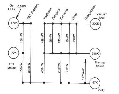 |
Figure D-8. Heat map derived from a detailed cryostat thermal model. |
Recently, with NASA SR&T funding we (UCB and GSFC) have conducted tests for noise in the GeDs due to microphonics and electrical pickup from the Sunpower cooler. A coaxial GeD in the standard UCB module was mounted on a coldplate connected with a flexible thermal "S-link" to the cold tip of the cooler (the configuration for HESSI). The cooler was run open-loop, without active vibration damping in the tests. Microphonic and electrical pick-up noise was found to be negligible, with no significant (<0.1 keV) difference in the GeD energy resolution or noise background with the Sunpower on or off.
The cryocooler electronics provides autonomous startup and shutdown, efficient DC-AC power, and temperature/piston stroke control. These will be packaged separately and mounted near the mechanical cooler.
D.2.a.3. Instrument Electronics
Each GeD is biased at between 4 and 5 kV by a separate adjustable HVPS (developed at UCB for FAST/SMEX and HIREGS). Photons interacting in a GeD generate charge pulses, which are collected and amplified by a transistor-reset Charge Sensitive Amplifier (CSA) (developed by UCB for HIREX) (Fig. D-9) to provide the best resolution and high-count rate performance, and to avoid problems associated with pole-zero cancellation. The FET is an advanced 4-terminal type (developed for UCB and baselined for the ESA INTEGRAL mission) with 3-4 times the gain and half the capacitance of available commercial units.The CSA signal from the GeD front segment goes to two parallel signal processing chains (Fig. D-9). The high resolution "slow" chain consists of a 9-pole quasi-trapezoidal filter amplifier with a peaking time of 4 µsec (developed by UCB), a peak stretcher, and a 16-bit successive approximation ADC (flown on HIREGS). To maintain optimum resolution at high energies >~1 MeV, quasi-trapezoidal filtering is needed to compensate for ballistic deficit effects of the charge collection in large GeDs. The upper 13 bits of the ADC provide 8192 channels of spectral measurements from ~3 keV to 2.7 MeV with ~0.33 keV/channel at rates up to 50,000 c/s.
The high rate "fast" chain (developed for HIREGS) consists of a delay-line shaper generating a triangular pulse of 0.5 µs duration (count rate capability >500,000 c/s), which is sent to a 4-channel stacked discriminator ADC. When the slow chain saturates (Fig. D-5), the accumulated output of these four channels will be sampled at a rate of 16 kHz to provide broad-band (deltaE/E ??1) imaging. The fast channel LLD signal is used to detect front-rear and GeD-GeD coincidences, and for pulse pileup rejection.
The GeD rear segment has two amplifiers in the slow chain, a normal and a low gain (Fig. D-9), as in HIREGS. The ULD at 2.7 MeV switches the 16-bit ADC to the low gain amp to provide ~2.4 keV/channel up to 20 MeV.
Data formatting follows that for HIREGS. For each detected photon, 14-bits of energy and time of arrival (to 60 µs) are encoded together with detector identification and coincidence flags into a 24-bit event word. This word is latched and a flag raised to signal the formatter card, (based on a FAST design) which simultaneously transfers and formats event data into CCSDS frames. These are sent to the spacecraft mass memory system.
Data Storage
Normally every photon is stored and then sent down. If an extended extremely active period occurs, the main limitation is the orbit-averaged downlink rate. The GeD rear segments' event rate is always low enough to be stored. When the memory approaches full, the GeD front segments are subsampled by collecting events for an integral number of half-spins for full angular coverage to produce an image, and then not sampling until the input rate matches the expected downlink rate. This method keeps the mass memory from overflowing, with minimum loss of imaging and no loss in gamma-ray spectroscopy. Of course, a second ground station could be used to dump the data more rapidly if needed.
Figure D-9. Block diagram of the instrument electronics.
D.2.a.4. Calibration and Test
The GeDs are calibrated with a set of radioactive sources ranging from soft X-rays to ~2.6 MeV. Energies up to 15 MeV are obtained using neutron-gamma sources. After integration of the Spectrometer, measurements with radioactive sources are made over a range of energies and angles to calibrate a detailed GEANT Monte Carlo model of the Spectrometer with the precise geometry and all materials, as was done for HIREGS and HEXAGONE. This model provides a detailed instrument response for data analysis.After the Imaging System and Spectrometer have been independently integrated into the spacecraft, radioactive sources are again used to measure total transmission through the grid pairs, and confirm the GeD calibrations.
A calibration pulse generator injects a precisely generated charge pulse into the CSA at ~0.3 Hz for GeD electronics calibration and monitoring. During test mode, this pulser provides a precisely timed pattern of pulses to mimic imaging. These test images are used to check the entire electronics chain, onboard software, and imaging software on the ground.
A final test will be conducted prior to launch to provide end-to-end verification of the performance by determining the modulation amplitude provided by each grid pair in response to a moving X-ray source. For this test, a small gold-foil `gridlet' will be used to define the geometry of an ~100-microcurie source of X-rays (e.g., 109Cd). For suitable distances from the front grids (typically 1-2 m), the gridlet geometry is selected so that PC-controlled motion of the gridlet/source assembly produces strong and calculable modulation in the transmitted photon flux through each grid pair in turn. Data on the X-rays detected with the germanium detectors are recorded and pass through the complete flight data system. The measured modulation as compared to the expected modulation for each grid pair gives an accurate indication of overall performance of the Imaging System.
In-flight, systematic studies of many solar bursts can provide excellent self-calibration, as shown by Yohkoh HXT, and separating out the pulsed emission from the Crab provides a point-source calibration. Ge background lines provide excellent absolute gain calibration.
D.2.b.Mission
The requirements imposed by HESSI on the spacecraft (Table F-2) can be met by a simple Sun-pointed, spin-stabilized spacecraft. The instrument field of view (>~° ) is much larger than the Sun (0.5° ) so spacecraft pointing is relaxed and can be automated. The instrument is on continuously. All of the photon data for the largest flare can be stored in the spacecraft memory and downlinked in <~48 hours, so flare data will rarely, if ever, be lost. Consequently, HESSI is planned for an automated store-and-dump operation, and normally no real-time access is required.The 600 km circular, 38° inclination orbit can be provided by a standard SELVS II launch. A single LEO-T ground station at UCB provides the required data downlink rate (~1 Gbyte/day), and minimizes tracking, data transmission, and operation costs while allowing the involvement of many students (as in EUVE and FAST). Both the instrument and spacecraft are designed to operate autonomously for weeks at a time, so a single-shift, 5-day-a-week staffing is sufficient.
Launch Date
Figure D-10 shows the predictions of the integrated total number of solar hard (>20 keV) X-ray and gamma-ray (>300 keV) flares occurring in a two-year nominal HESSI mission, based on the observations of the previous two cycles and the mean period for the last seven cycles of 10.5 years. Even with the uncertainty of ± 1 year in the predictions, a HESSI launch in mid 2000 as the first of the two SMEX missions selected by this AO, would be ideal. A launch in 2001 would still be acceptable.
Figure D-10. The predicted 2-year integrated total number of flares, above 25 keV and above 300 keV, versus launch date (July 2000 planned) (based on HXRBS, BATSE, and Phebus observations).
D.2.c. Data Analysis and Archiving
HESSI differs from many imagers in that, instead of transmitting a preselected subset of images, the telemetry includes all of the information about each detected photon. Thus, the data analyst can make tradeoffs among time resolution, spectral range and resolution, spatial resolution, image quality, etc., on the ground. These decisions can be made on a case-by-case basis to match the unique characteristics of the event under study and the relevant scientific objective. A key driver of our data analysis approach is the preservation of this flexibility so as to extract the maximum scientific return from the observations. This means that all detailed scientific analysis will use the same primary database with the most current calibration information.In implementing this approach for HESSI data reduction and analysis, we plan for: 1) the complete data output of the HESSI mission to be made available promptly to the scientific community, without restriction; and 2) a fully documented analysis package, supported by a range of platforms, to be available to the scientific community, with the same toolbox of software used by the PI team. A promptly-generated catalog of summary data products will be distributed with the HESSI data base, to serve as a multi-parameter index and overview of the data base and to provide data products to users not requiring custom analyses. Table D-4 lists the specific data products from this effort and the responsible team members.
Table D-4. Data Products
| Data Product | Responsible Individual |
| Primary data base | Smith |
| Flare list | Schwartz |
| Flare light curves | Schwartz |
| Imaging calibration | Hurford |
| Reconstructed images | Hurford |
| Spectroscopy calibration | Slassi |
| X-ray spectra | Schwartz |
| Gamma-ray spectra | Smith |
| Complementary data | Zarro |
| Software distribution /documentation | Tolbert |
Data Flow and Distribution
The data flow will follow the FAST model that was designed to minimize interfaces and the production of extensive secondary data bases. Data will be telemetered directly from the spacecraft to the MOC/SOC at UCB, where the raw telemetry files will be reformatted into the primary data base. This includes the following principal elements: time-tagged photons, SAS and RAS data, and housekeeping data. Health, safety, and status are confirmed using automated algorithms at this stage. As with FAST, to ensure prompt preparation, the primary data base is generated without routine operator intervention and with no value added except for the addition of "catalog" information. This will include pointers to make the primary data base appear as a sequence of time-ordered, non-duplicated, and quality-flagged data, a summary of spacecraft/instrument status, detector rates above representative energy thresholds, and orbital averages of full-resolution spectra.For solar events, sets of representative images and spatially integrated spectra will be generated using robust algorithms for inclusion in the catalog. The primary data base and catalog will be made available by network access using a CD-ROM jukebox, and will be shipped to GSFC and ETH on CD-ROMs daily.
At GSFC, the HESSI solar data analysis, distribution, and archiving tasks will be conducted under the auspices of the Solar Data Analysis Center (SDAC). We will take full advantage of the SDAC facilities and experienced personnel developed through the coordinated analysis of data from SMM, Yohkoh, CGRO, and SOHO. In addition to HESSI data, the SDAC will also maintain a database of other relevant spacecraft and ground-based observations.
A detailed data time line is given in Table D-5. The primary data base and the quick-look data products will be available on line, typically within 24 hours of receipt at UCB. All data products, including the latest analysis software and calibration data, will be shipped to the NSSDC on high-density magnetic tape for archiving within 2 months of real time.
| Process | Time Required |
| Data telemetered to UCB | 0-48 hrs |
| Reformat primary data base and generate catalog | <= 3 hrs |
| Generate CDs and ship to GSFC and ETH. Data on line at UCB | <= 24 hrs |
| Data products to NSSDC | <= 2 months |
Software Development
The overall HESSI ground software development task can be divided into three areas:- Software for prelaunch system-level testing and post-launch operations. Its purpose is primarily command generation, status display, and generation of the primary data base. This software will be developed at UCB based on FAST.
- Prelaunch software associated with subsystem testing and calibration, developed by the group responsible for the corresponding subsystem.
- Post-launch analysis software will be coordinated at GSFC, where careful attention will be paid to optimizing user and data interfaces across the different elements.
We have allocated substantial resources to the software development effort to ensure that the data analysis tools will be fully debugged, documented, and tested prior to launch. Our language of choice is IDL. It is easily maintained, well suited to rapid development, can operate seamlessly on many different platforms, and is widely used throughout the solar and astrophysical communities (e.g., Yohkoh and CGRO), allowing us to take advantage of the significant investment in a large body of pre-existing software.
D.2.d Science Team Roles and Responsibilities
The capabilities and experience of Science Team members are given in Appendix I-1.
Professor Robert Lin at UCB will lead the Science Team as PI and have overall responsibility for the HESSI mission. Dr. Brian Dennis is the lead Co-I in charge of the overall GSFC effort. Professor Lin and Dr. Dennis were Chairman and Study Scientist respectively for NASA's HESP and HESI (precursors to HESSI) Science Study Team. Dr. Alex Zehnder is the lead Co-I in charge of the PSI hardware and data analysis effort. No NASA funding is required for the PSI (Switzerland) effort. Co-I Gordon Hurford will be the Imager Scientist in charge of Imaging system design and test, and image reconstruction software. UCB Associate Scientist Dr. David Smith will be the Spectrometer Scientist, with responsibility for overall Spectrometer development, testing, and gamma-ray spectral analysis software.
At UCB, Co-I Mr. Norm Madden will lead the GeD and front end electronics development. Associate Scientist Dr. Said Slassi will lead the Spectrometer calibration, modeling and software effort. Associate Scientist Dr. James McTiernan will be the scientist supervising the MOC/SOC operations and participating in the science software effort. Associate Scientist Dr. George Fisher will lead the UCB theory and modeling effort. Associate Scientist Dr. Isabel Hawkins will lead the UCB Education Outreach effort and coordinate it with her Sun-Earth Connection Education/Outreach program. All of them will participate in the UCB data analysis effort.
At GSFC, Co-I Dr. Carol Crannell will lead GSFC's Education/Outreach effort. Co-I Dr. Reuven Ramaty will lead the theory and modeling effort for gamma -ray spectroscopy and Co-I Dr. Gordon Holman for flare energy release and particle acceleration. Co-I Dr. Tycho von Rosenvinge will be in charge of ACE/HESSI joint data analysis. Associate Scientist Dr. Larry Orwig will lead the grid characterization effort. Associate Scientist Dr. Richard Schwartz will lead the X-ray spectral analysis effort. Associate Scientist Dr. Dominic Zarro will be in charge of the complementary data. All of them will participate in the GSFC data analysis effort.
At the University of Maryland, Associate Scientists Dr. Ed Schmahl and Dr. Markus Aschwanden will provide imaging and timing analysis software respectively. Co-I Professor Richard Canfield of Montana State University will be the Ground-based Observations Coordinator. Co-I Dr. Hugh Hudson will be in charge of white light image alignment software and also participate in analysis of X-ray images. At U. Alabama Huntsville, Co-I Professor Gordon Emslie will provide theory and modeling of particle acceleration, transport, and loss processes in flares. Co-I Professor Frank van Beek at Delft will provide the stacked grids and mounts, and consultation on fine mechanical engineering.
The following CoIs do not require NASA funding. Co-I Dr. Pat Bornmann at NOAA will lead the GOES/HESSI data analysis and studies related to LSEP event prediction.Co-I Professor Arnold Benz will head up the High Energy Data Center in ETH/Zurich for distribution of HESSI data and context ground observations. Co-I Dr. Nicole Vilmer will lead the analysis, imaging software, and coordination with radio observation effort at Meudon. Co-I Professor John Brown will lead the U. Glasgow theory and modeling effort, concentrating on the X-ray-to-electron inversion problems. At NAOJ, Co-I Professor Takeo Kosugi will lead the Japanese effort on hard X-ray imaging analysis, and Co-I Dr. Shinzo Enome will concentrate on campaigns with radio observations.


